An ignition switch wiring diagram provides a detailed visual representation of electrical connections within an ignition system‚ helping users understand how components like the ignition switch‚ starter motor‚ and battery interconnect for proper functionality.
1.1 What is an Ignition Switch Wiring Diagram?
An ignition switch wiring diagram is a visual guide that illustrates the electrical connections and components of an ignition system. It details how the ignition switch‚ starter motor‚ battery‚ and other related components are interconnected. This diagram is essential for understanding the flow of power and signals within the system. It typically includes symbols‚ wire color codes‚ and labels to represent each part. Whether for installation‚ troubleshooting‚ or repairs‚ the diagram serves as a blueprint for ensuring proper functionality. By following the diagram‚ users can identify and resolve issues efficiently‚ making it an indispensable tool for automotive enthusiasts and professionals alike.
1.2 Importance of Using a Wiring Diagram for Ignition Systems
Using a wiring diagram for ignition systems is crucial for ensuring safety‚ accuracy‚ and efficiency. It provides a clear visual representation of the electrical connections‚ helping users avoid mistakes during installation or repairs. A diagram prevents short circuits and ensures proper power distribution to components like the ignition switch‚ starter motor‚ and battery. It also aids in troubleshooting by identifying faulty connections or components. By following the diagram‚ users can save time and money‚ reducing the risk of costly repairs. Additionally‚ it serves as a reference for future maintenance or upgrades‚ making it an essential tool for both professionals and DIY enthusiasts working with ignition systems.
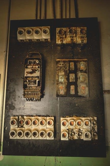
Key Components in an Ignition Switch Wiring Diagram
A wiring diagram outlines the fundamental elements and their interconnections‚ ensuring clarity for installation‚ troubleshooting‚ and repairs of the ignition system.
2.1 Ignition Switch
The ignition switch is the central component in the wiring diagram‚ responsible for controlling the flow of electrical power to the vehicle’s ignition system. It typically features multiple terminals‚ including the battery terminal‚ ignition terminal‚ starter terminal‚ and accessory terminal. These terminals connect to various parts of the system‚ such as the starter motor‚ ignition coil‚ and accessories like the radio or lights. The switch operates by routing power through these connections based on its position‚ whether it’s off‚ on‚ or in the start position. Understanding the ignition switch’s wiring is crucial for diagnosing issues and ensuring proper system functionality. Always refer to the wiring diagram for accurate connections to avoid electrical problems.
2.2 Starter Motor
The starter motor is a critical component in the ignition system‚ responsible for turning the engine over during startup. It is directly connected to the ignition switch and battery through the wiring diagram. The starter motor receives a high current from the battery when the ignition switch is in the “start” position‚ engaging the solenoid to activate the motor. Proper wiring ensures the starter motor functions only when the ignition is in the correct position‚ preventing accidental engagement. The wiring diagram illustrates the connections between the starter motor‚ ignition switch‚ and starter relay‚ ensuring safe and efficient operation. Always consult the diagram for accurate wiring to avoid electrical issues.
2.3 Battery
The battery serves as the primary power source for the ignition system‚ providing the necessary voltage to operate the starter motor and other electrical components. It is connected directly to the ignition switch and starter relay through the wiring diagram. The battery’s positive terminal is typically linked to the ignition switch’s “hot” wire‚ while the negative terminal connects to the vehicle’s chassis or grounding system. Proper wiring ensures consistent power delivery‚ preventing electrical surges or failures. The wiring diagram highlights the battery’s role as the foundation of the ignition system‚ emphasizing the importance of correct connections for reliable engine startup and operation. Always refer to the diagram to ensure safe and accurate wiring.
2.4 Wire Color Codes
Wire color codes are essential for identifying connections in an ignition switch wiring diagram. These codes help technicians and DIYers understand which wires perform specific functions‚ ensuring accurate and safe wiring. Common colors include red for positive power‚ black for ground‚ and yellow for ignition circuits. While standard color codes exist‚ variations can occur between manufacturers‚ so it’s crucial to consult the vehicle’s specific wiring diagram. Misidentifying wires can lead to electrical malfunctions or damage. Always verify the color codes against the manufacturer’s guide to ensure proper connections and avoid potential hazards. This step is critical for maintaining the integrity of the ignition system.
2.5 Starter Relay
The starter relay is a crucial component in the ignition system‚ acting as an intermediary between the ignition switch and the starter motor. It handles high current flows‚ protecting the ignition switch from potential damage. In a wiring diagram‚ the starter relay is typically represented by a rectangular symbol with terminal connections labeled. These terminals usually include one for the ignition switch input‚ one for the battery power source‚ and one for the starter motor output. Wire color codes‚ such as red for power and yellow for ignition signals‚ help identify connections. Proper wiring of the starter relay ensures smooth engine starting. Always refer to the manufacturer’s guide for specific configurations. A faulty relay can prevent the engine from starting‚ making it a key diagnostic point.

Types of Ignition Switches
Ignition switches vary‚ including 4-pole‚ standard‚ and aftermarket options‚ each designed for specific applications‚ ensuring reliable control over engine starting and accessory systems.
3.1 4-Pole Ignition Switch
A 4-pole ignition switch is a common type used in automotive applications‚ offering four distinct electrical connections. It typically controls the ignition system‚ accessories‚ starter motor‚ and off positions. This switch is known for its durability and versatility‚ making it suitable for both standard and modified vehicles. The wiring diagram for a 4-pole switch usually illustrates the connections for power‚ ground‚ and accessory circuits. Proper installation ensures smooth operation of the vehicle’s electrical systems. Always refer to the manufacturer’s wiring diagram for specific connections to avoid malfunctions.
3.2 Standard Ignition Switch
A standard ignition switch is a fundamental component in most vehicles‚ designed to control the flow of electrical power to the ignition system. Typically featuring three or four positions‚ it allows the driver to start the engine‚ power accessories‚ and shut off the system. The switch is usually connected to the starter motor‚ ignition coil‚ and accessory circuits. Wiring diagrams for standard ignition switches are essential for proper installation and troubleshooting. They detail the connections for power‚ ground‚ and accessory wires‚ ensuring safe and efficient operation. Always refer to the manufacturer’s specifications to avoid electrical issues and ensure compatibility with your vehicle’s system.
3.3 Aftermarket Ignition Switches
Aftermarket ignition switches offer enhanced functionality and customization for vehicles‚ providing improved durability and advanced features compared to standard switches. They are designed to fit various vehicles‚ with options for universal or vehicle-specific applications. These switches often include additional features such as LED indicators‚ multiple power outputs‚ and programmable settings. Wiring diagrams for aftermarket switches are crucial for proper installation‚ ensuring compatibility with the vehicle’s electrical system. They detail the connections for power‚ ground‚ and accessory circuits‚ making it easier to integrate modern accessories. Always consult the manufacturer’s wiring diagram to avoid electrical issues and ensure optimal performance. Aftermarket switches are a popular choice for custom builds and upgrades.

Safety Precautions When Working with Ignition Wiring
Always disconnect the battery to prevent electrical shocks or short circuits. Use proper tools and follow the wiring diagram to avoid damage or fire hazards.
4.1 General Safety Guidelines
When working with ignition wiring‚ always disconnect the battery to prevent electrical shocks or accidental engine start-ups. Use insulated tools to avoid short circuits and ensure proper grounding. Wear protective gear‚ including gloves and safety glasses‚ to safeguard against sparks or flying debris. Never bypass safety features or skip steps outlined in the wiring diagram. Keep flammable materials away from the work area to reduce fire risks. If unsure about any step‚ consult a professional or the vehicle’s manual. Properly secure loose wires to prevent damage or interference with other components. Follow all local safety regulations and best practices for automotive electrical work.
4.2 Specific Safety Tips for Ignition Wiring
When working with ignition wiring‚ always refer to the wiring diagram specific to your vehicle to avoid incorrect connections. Use the correct tools‚ such as insulated screwdrivers‚ to prevent short circuits. Never work on live circuits; always disconnect the battery first. Avoid touching electrical components with bare hands to prevent static discharge. Secure all wires properly to prevent chafing or damage from moving parts. Be cautious of ignition components‚ as they may retain voltage even after the system is turned off. Double-check all connections before reconnecting the battery to ensure safety and proper functionality. Follow the wiring diagram meticulously to avoid miswiring‚ which can lead to system failure or fire hazards.
Step-by-Step Guide to Wiring an Ignition Switch
Disconnect the battery to ensure safety. Connect the ignition switch wires according to the wiring diagram‚ ensuring power‚ ground‚ and accessory wires are correctly linked. Test the system thoroughly after completion.
5.1 Tools and Materials Needed
To wire an ignition switch‚ you’ll need essential tools and materials. Start with a multimeter for testing connections‚ wire cutters‚ and strippers for preparing wires. Use high-quality connectors and crimping tools to ensure secure connections. A soldering iron and heat shrink tubing can provide durable‚ long-lasting joints. Additionally‚ gather the ignition switch‚ wiring harness‚ and a battery. Refer to your specific ignition switch wiring diagram for any vehicle-specific components. Always use insulated tools to prevent short circuits. Having a well-organized workspace with all materials ready will streamline the process and reduce the risk of errors during installation.
5.2 Connecting the Battery
Connecting the battery is a critical step in wiring an ignition switch. Ensure the ignition is in the off position before starting. Locate the positive (+) and negative (-) terminals on the battery. Connect the positive terminal to the ignition switch using a heavy-gauge wire‚ as specified in your ignition switch wiring diagram. The negative terminal should be connected to the engine block or chassis to provide a proper ground. Use appropriate connectors and ensure all connections are tight to avoid electrical issues. Always disconnect the battery when working on electrical systems to prevent shocks or short circuits. Refer to your wiring diagram for specific connections and wire color codes.
5.3 Wiring the Ignition Switch
Wiring the ignition switch involves connecting the appropriate wires to ensure proper functionality. Refer to your ignition switch wiring diagram to identify the correct terminals. Typically‚ the ignition switch has terminals for power input‚ output to the starter relay‚ and accessory circuits. Connect the battery wire to the power input terminal‚ and the starter relay wire to the output terminal. Accessory wires‚ such as those for lights or radios‚ should be connected to the accessory terminal. Use the correct wire color codes to avoid confusion. Ensure all connections are secure and insulated to prevent short circuits. Always disconnect the battery before starting work to ensure safety. Follow the diagram carefully to avoid miswiring‚ which could damage the ignition system or other components.
5.4 Testing the Ignition System
After wiring the ignition switch‚ reconnect the battery and test the ignition system. Turn the ignition key to the “ON” position and check if the dashboard lights illuminate. Ensure all accessories‚ like the radio or lights‚ function properly. Next‚ turn the key to the “START” position to verify the starter motor engages and the engine turns over. If the engine starts‚ allow it to run briefly to confirm smooth operation. Use a multimeter to check for proper voltage at the ignition switch terminals. If issues arise‚ consult the ignition switch wiring diagram to trace connections and identify potential faults. Testing ensures the system operates safely and efficiently.

Troubleshooting Common Issues
Common issues include no power to the ignition system‚ intermittent switch problems‚ or blown fuses. Consult the wiring diagram to identify faulty connections or components. Use a multimeter to diagnose electrical issues and ensure proper voltage supply. Check for loose wires‚ corrosion‚ or damaged insulation. Replace faulty parts and test the system again to confirm resolution. Regular maintenance and adherence to safety guidelines can prevent recurring problems and ensure reliable ignition system performance.
6.1 No Power to the Ignition System
No power to the ignition system is a common issue that can prevent the vehicle from starting. This problem often arises due to a blown fuse‚ a faulty ignition switch‚ or a disconnected battery. To diagnose‚ consult the wiring diagram to trace the ignition circuit. Use a multimeter to test for voltage at the ignition switch and battery terminals. Check for loose or corroded connections‚ especially at the battery and starter motor. Ensure the ignition switch is functioning correctly by testing its continuity. If the issue persists‚ verify the starter relay and ignition coil connections. Referencing the wiring diagram can help identify the root cause and guide repairs effectively.
6.2 Intermittent Ignition Switch Problems
Intermittent ignition switch issues can cause frustrating and unpredictable starting problems. These problems often stem from a faulty ignition switch‚ loose connections‚ or worn-out internal components. To diagnose‚ use a multimeter to test the switch’s continuity and ensure it activates the starter motor and ignition coil properly. Check for loose wires or corrosion at the switch terminals. If the issue persists‚ consider replacing the ignition switch. Always refer to the wiring diagram to verify connections and ensure proper installation. Intermittent problems can escalate‚ so addressing them promptly is crucial to avoid complete system failure and ensure reliable vehicle operation. Regular maintenance can help prevent such issues.
6.3 Blown Fuses or Tripped Circuit Breakers
Blown fuses or tripped circuit breakers are common issues that can disrupt the ignition system. These problems often occur due to short circuits‚ overloaded circuits‚ or faulty components. To resolve this‚ locate the fuse box using the wiring diagram and identify the fuse associated with the ignition system. Replace the blown fuse with one of the correct rating. If a circuit breaker trips‚ reset it after addressing the underlying cause. Always refer to the wiring diagram to ensure proper connections and avoid further damage. Regularly inspecting fuses and circuit breakers can help prevent such issues and maintain reliable ignition system performance. Addressing these problems promptly is essential for smooth vehicle operation.

Understanding Ignition Switch Wiring Diagram Symbols
Ignition switch wiring diagrams use standard symbols to represent components like switches‚ batteries‚ and starter motors. These symbols help technicians interpret and troubleshoot the wiring layout effectively.
7.1 Common Symbols Used in Wiring Diagrams
Wiring diagrams use standardized symbols to represent components‚ ensuring clarity and consistency. Common symbols include circles for switches‚ parallel lines for batteries‚ and coils for starter motors. Lines represent wires‚ with color codes indicating specific functions. These symbols are universally recognized‚ making it easier for technicians to interpret and troubleshoot ignition systems. Understanding these symbols is crucial for accurately following a wiring diagram‚ whether for installation‚ repair‚ or customization. They provide a visual language that transcends written instructions‚ ensuring that even complex systems can be understood and worked on efficiently. This standardization is key to safe and effective electrical work in automotive systems.
7.2 Interpreting Wire Color Codes
Wire color codes are essential for identifying the function of each wire in an ignition system. Common colors include red for the ignition switch‚ yellow for the starter motor‚ and black for ground connections. These codes ensure consistency across different vehicles and manufacturers‚ making it easier to trace and connect wires accurately. Understanding these codes helps technicians avoid mistakes during installation or repair. For example‚ a red wire typically carries power from the ignition switch‚ while a brown wire might connect to accessories like lights or radios. Always consult the manufacturer’s guide for specific color assignments‚ as variations can occur. Accurate interpretation ensures safety and proper system functionality.

Downloading and Using Ignition Switch Wiring Diagrams
Download your free ignition switch wiring diagram PDF for a comprehensive guide. Perfect for automotive enthusiasts and professionals‚ it simplifies installation and troubleshooting processes effectively.
8.1 Where to Find Reliable Wiring Diagrams
Reliable ignition switch wiring diagrams can be found in automotive repair manuals‚ manufacturer websites‚ or trusted online forums. Websites offering free PDF downloads are popular among enthusiasts. For specific models‚ such as the 2000 Chevy Silverado or Honda Gx390‚ official manufacturer resources are recommended. Additionally‚ automotive repair shops and dealerships often provide accurate diagrams. Ensure the source is reputable to avoid incorrect or misleading information. Always verify the diagram matches your vehicle’s make and model for precise connections and troubleshooting. Downloading from trusted sources ensures safety and reliability when working with electrical systems.
8.2 How to Download a Wiring Diagram PDF
To download a reliable ignition switch wiring diagram PDF‚ start by searching for the specific make and model of your vehicle. Use keywords like “ignition switch wiring diagram PDF” or “2000 Chevy Silverado ignition switch wiring diagram” for accurate results. Visit reputable websites‚ such as manufacturer portals or trusted automotive forums‚ to ensure the diagram is correct. Once found‚ locate the download button or link on the page. Save the PDF to your device for easy access. Always verify the diagram’s clarity and accuracy before use. This ensures safe and proper installation or troubleshooting of your ignition system.
8.3 Benefits of Using a PDF Wiring Diagram
Using a PDF wiring diagram offers several advantages for working with ignition systems. PDFs provide clear‚ high-resolution visuals of wiring connections‚ making it easier to identify components and trace circuits. They are also easily searchable‚ allowing quick access to specific sections. PDF diagrams are portable and can be accessed on various devices‚ ensuring convenience for mechanics and DIYers. Additionally‚ PDFs can be zoomed in for detailed views‚ reducing eye strain. They are also printable‚ enabling physical copies for hands-on work. Most importantly‚ PDF wiring diagrams are widely compatible and retain their formatting across devices‚ ensuring accuracy and reliability for troubleshooting or installation tasks.
Advanced Topics in Ignition Switch Wiring
Advanced ignition switch wiring involves custom configurations and integrating modern accessories like alarms or keyless systems‚ enhancing functionality while maintaining reliability and efficiency in electrical systems.
9.1 Custom Ignition Switch Wiring
Custom ignition switch wiring allows for tailored electrical setups‚ enabling the integration of modern accessories like alarms‚ keyless systems‚ or advanced dashboards. This involves modifying the standard wiring diagram to accommodate additional components while ensuring proper power distribution. By understanding the wire color codes and connections‚ enthusiasts can create unique configurations that enhance functionality. For instance‚ adding a remote start or immobilizer requires precise wiring adjustments. Using a wiring diagram PDF as a reference helps in planning and executing custom setups efficiently. Safety and compatibility must be prioritized to avoid electrical faults or system malfunctions. This approach is ideal for those seeking personalized vehicle enhancements.
9.2 Integrating Modern Accessories with Ignition Systems
Integrating modern accessories‚ such as alarms‚ keyless entry‚ or dash cams‚ with ignition systems enhances vehicle functionality and convenience. A wiring diagram PDF serves as a crucial guide‚ ensuring proper connections without disrupting the ignition circuit. When adding accessories‚ it’s essential to identify the correct wires‚ such as the accessory or constant power lines‚ to avoid electrical conflicts. Modern systems often require additional relays or modules‚ which must be wired according to the manufacturer’s specifications. This integration allows for seamless operation of aftermarket devices while maintaining the integrity of the ignition system. Proper planning and execution are vital to prevent malfunctions or electrical damage.
In conclusion‚ an ignition switch wiring diagram PDF is an essential tool for understanding and working with ignition systems safely and effectively‚ ensuring proper connections and functionality.
10.1 Summary of Key Points
An ignition switch wiring diagram PDF is crucial for understanding electrical connections in ignition systems‚ detailing components like the ignition switch‚ starter motor‚ and battery. It outlines wire color codes‚ ensuring proper connections and functionality. The diagram aids in troubleshooting issues such as no power or intermittent problems. Safety guidelines are emphasized to prevent accidents. Types of ignition switches‚ including 4-pole and standard models‚ are explained. The PDF format offers portability and clarity‚ making it ideal for DIY enthusiasts and professionals. By following the diagram‚ users can install‚ repair‚ and customize ignition systems effectively‚ ensuring reliability and performance. It serves as a comprehensive guide for anyone working with automotive electrical systems.
10.2 Final Tips for Working with Ignition Wiring Diagrams
Always refer to a reliable ignition switch wiring diagram PDF for accurate connections and safety. Use the correct tools and materials to avoid damage or short circuits. Test the system step-by-step after wiring to ensure proper functionality. Prioritize safety by wearing protective gear and ensuring the ignition is off during work. Double-check all connections and wire color codes before powering up. If unsure‚ consult the manufacturer’s instructions or seek professional assistance. Regularly inspect wires for wear or damage to prevent issues. By following these tips‚ you can ensure a safe and successful ignition system installation or repair‚ achieving optimal performance and reliability.

